Several months ago started the GSoC 2017. Among all the projects available one got my attention:
Add OpenGL support on a Windows guest using VirGL
In a VM, to access real hardware, we have two methods: passthrough, and virtualization extensions (Intel VT-x, AMD-V..).
When it comes to GPUs possibilities drop down to one: passtrough.
Intel has a virtualization extension (GVT), but we want to support every devices.
Thus, we need to fall-back to a software based method.
- Emulation ? Since we want 3D acceleration, better forget it
- API-forwarding ? This means we need to have the same OpenGL API between guest host, also no.
- Paravirtualization ? Yes !
Since a couple years, VirtIO devices became a good standard on QEMU.
Then, Dave Airlie started to work on VirGL and a VirtIO-gpu.
Both help provide a descent virtual-GPU which rely on the host graphic stack.
This article will present VirtIO devices, and what kind of operations a guest can do using VirGL.
I also invite you to read a previous article I wrote about Linux’s graphic stack
VirtIO devices
Since we will use a VirtIO based device, let’s see how it works.
First, these devices behave as regular PCI devices. We have a config space, some dedicated memory, and interruptions.
Second very important point, VirtIO devices communicate with ring-buffers used as FIFO queues.
This device is entirely emulated in QEMU, and can realize DMA transfers by sharing common pages between the guest and the host.
Communication queues
On our v-gpu, we have 2 queues. One dedicated to the hardware cursor, and another for everything else.
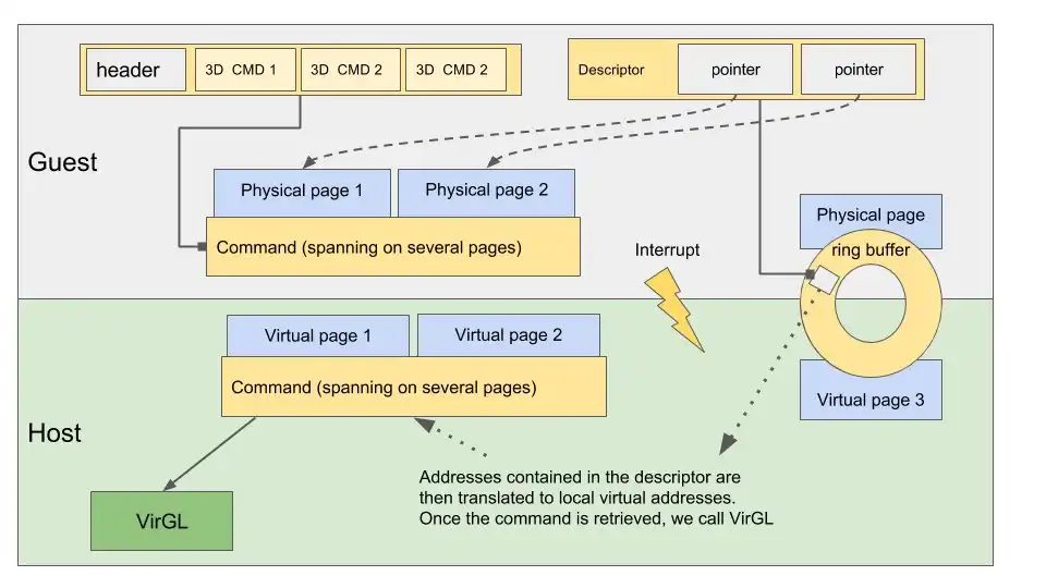
To send a command in the queue, it goes like this:
- guest: allocate pages on the host
- guest: send a header and pointers to our physical pages (guest POV) in the ring buffer.
- guest: send an interruption
- VMExit
- host: QEMU read our header and pointers. Translate addresses to match local virtual address range.
- host: read the command, execute it
- host: write back to ring buffer
- host: send interruption
- guest: handle interruption, read ring buffer and handle answer
VirGL
VirGL can be summed up as a simple state-machine, keeping track of resources, and translating command buffers to a sequence of OpenGL calls.
It exposes two kinds of commands: let’s say 2D and 3D.
2D commands are mainly focused on resources management. We can allocate memory on the host by creating a 2D resource. Then initialize a DMA transfer by linking this resource’s memory areas to guest’s physical pages.
To ease resource management between applications on the guest, VirGL also adds a simple context feature. Resource creation is global, but to use them, you must attach them to the context.
Then, 3D commands. These are close to what we can find in a API like Vulkan. We can setup a viewport, scissor state, create a VBO, and draw it.
Shaders are also supported, but we first need to translate them to TGSI; an assembly-like representation. Once on the host, they will be re-translated to GLSL and sent to OpenGL.
You can find a part of the spec on this repository
OpenGL on Windows
Windows graphic stack can be decomposed as follows:
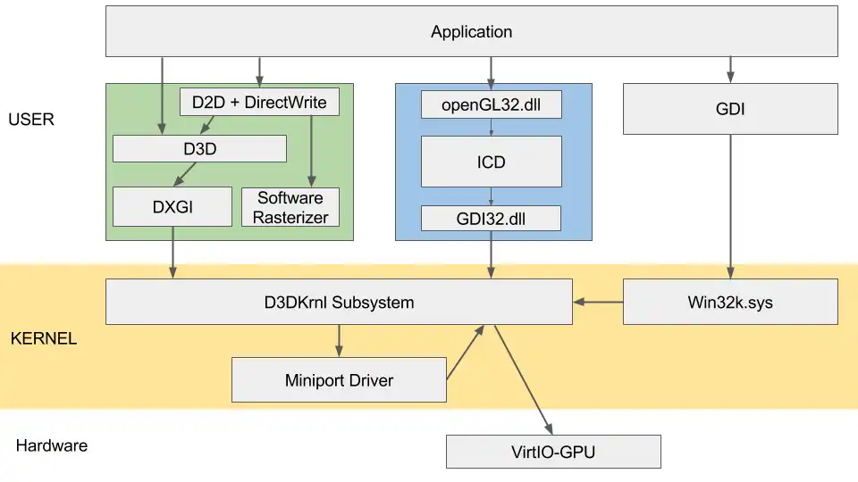
Interresting parts are:
OpenGL ICD (Installable client driver):
This is our OpenGL implementation -> the state machine, which can speak to our kernel driver.
GDI.dll:
A simple syscall wrapper for us.
D3D Subsystem:
First part of the kernel graphic stack. It exposes a 3D and 2D API. Since we are not a licensed developer, let’s try to avoid this.
From the documentation, we have a some functions to bypass it: DxgkDdiEscape is one.
This functions takes a buffer, a size, and lets it pass trough this subsystem, directly to the underlying driver.
DOD (Display Only Driver)
Our kernel driver. This part will have to communicate to both kernel/ICD and VirtIO-gpu.
OpenGL State-Tracker
OpenGL rely on a state machine we have to implement. Let’s start by drawing on the frame-buffer.
We start a new application, want to split it from the rest. So we start by creating a VirGL context.
Then create a 2D resource (800x600 RGBA seams great), and attach it to our VGL-context.
We might want to draw something now. We have two options, either use the 3D command INLINE_WRITE, or DMA.
Using INLINE_WRITE means sending all our pixels through a VirtIO queue. So let’s use DMA !
- We start by allocating our memory pages on the guest.
- Then, send physical addresses to VirGL (guest POV)
- VirGL will translate PA addresses to local virtual addresses, and link these pages to our resource.
- Back to the guest, we can write our pixels to the frame-buffer.
- To notify the V-gpu, we use the TRANSFER_TO_HOST_2D command, which tells QEMU to sync resources.
Now, let’s draw some pixels on this frame-buffer.
We will need :
- create an OpenGL context
- setup our viewport and scissor settings (ie: screen limits)
- create a VBO
- link the VBO to a vertex/normals/color buffer
- create vertex and frag shaders
- setup a rasterizer
- setup the frame-buffer to use the one we created earlier
- create a constant buffer
- send the draw call
A 3D Command is a set of UINT32. The first one is used as a header, followed by N arguments.
A command buffer can contains several commands stacked together in one big UINT32 array.
Earlier, we created resources in VGL-Contexts. Now we will need 3D objects.
These are created sending 3D commands, and are not shared between VGL contexts.
Once created, we have to bind them to the current opengl-context.
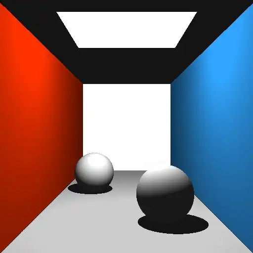
Now, if everything goes well, we should be able to display something like that:
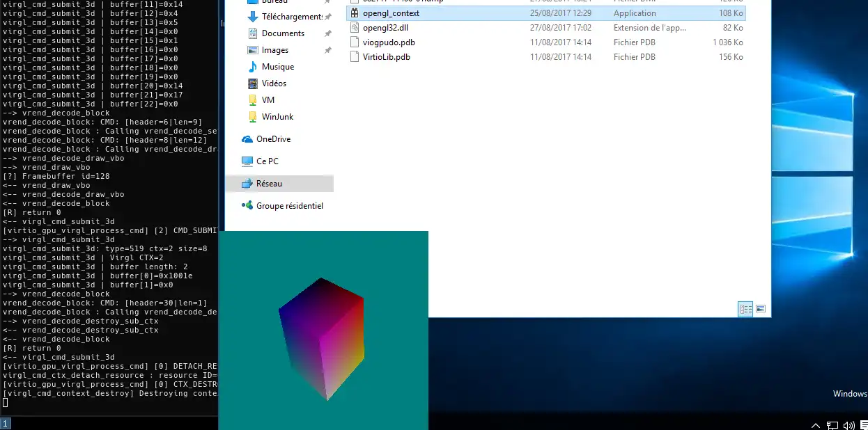
Once more, explaining all the commands would be uninteresting, but there is a spec for that !
If you are still interested, here are couple of links:
